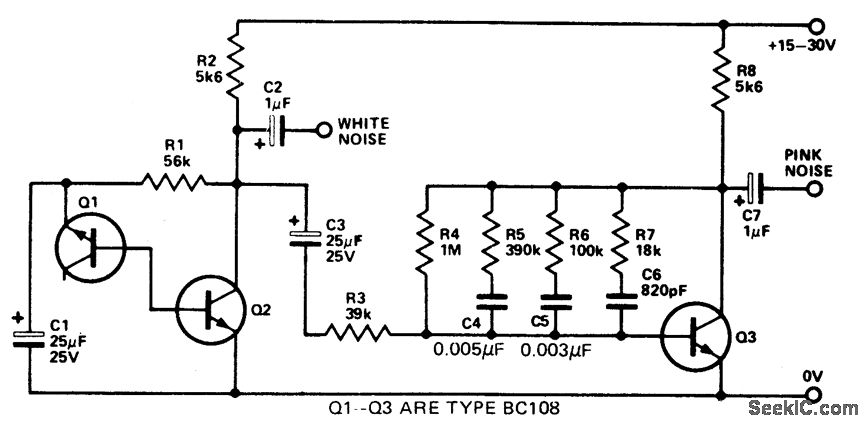
AUDIONOISEGENERATOR Circuit Diagram The output level of the sine wave signal is around 500mV RMS. 3) Using Audio Amplifier LM380. The circuit is built around an audio power amplifier device (IC1) utilized in a phase shift oscillator circuit. A three-section phase shift circuit is used to provide feedback between the output and the inverting (−) input of IC1.
- Tied a signal mode to CHANnel; so, now you may change signal form along with the frequency. - Slightly changed navigation. - Use EEPROM to store and recover settings. - Added a new signal mode: square/meander signal wave at 1/2 frequency (for even more accuracy of the output signal frequency). This is a standard feature of AD9833 module. A tone generator circuit can be used for various applications such as alarms, bells, indicators, etc. A tone generator consists of a square, triangle, sawtooth periodic wave generator circuits, commonly square wave generators. Such periodic signals produce a beeping sound when connected to audio transducers such as a speaker, piezo, etc.
How to Build Your Own Function Generator Using Analog Devices' AD9833 Circuit Diagram
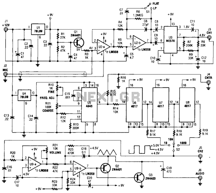
1) Using IC 4049. Using only one low-cost CMOS IC 4049 and a handful of separate modules, it is easy to create a robust function generator that will provide a range of three waveforms around and beyond the audio spectrum.. The purpose of the article was to create a basic, cost-effective, open source frequency generator that is easy to construct and used by all hobbyists and lab professionals.
.jpg)
Working Explanation. The operation of this circuit is based on the working principle of a self-triggering oscillator (astable multivibrator), performed by a 555 precision timer circuit (NE555).When the circuit is powered on, The values of resistors (R1, R2) & capacitors (C1, C2) on the left side of the circuit set the pitch of the output tone coming from the audio transducer (loudspeaker
Audio Signal Generator Circuit Diagram
Creating an audio signal generator circuit diagram may seem intimidating and complicated, but with a little bit of knowledge and some practice, anyone can gain the skills necessary to get it done. By following this guide and understanding the basics, it's possible to create your own audio signal generators and reap the many benefits they can offer.