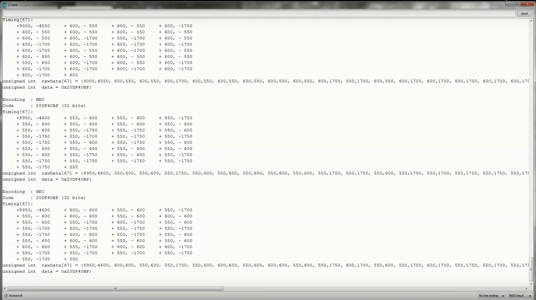
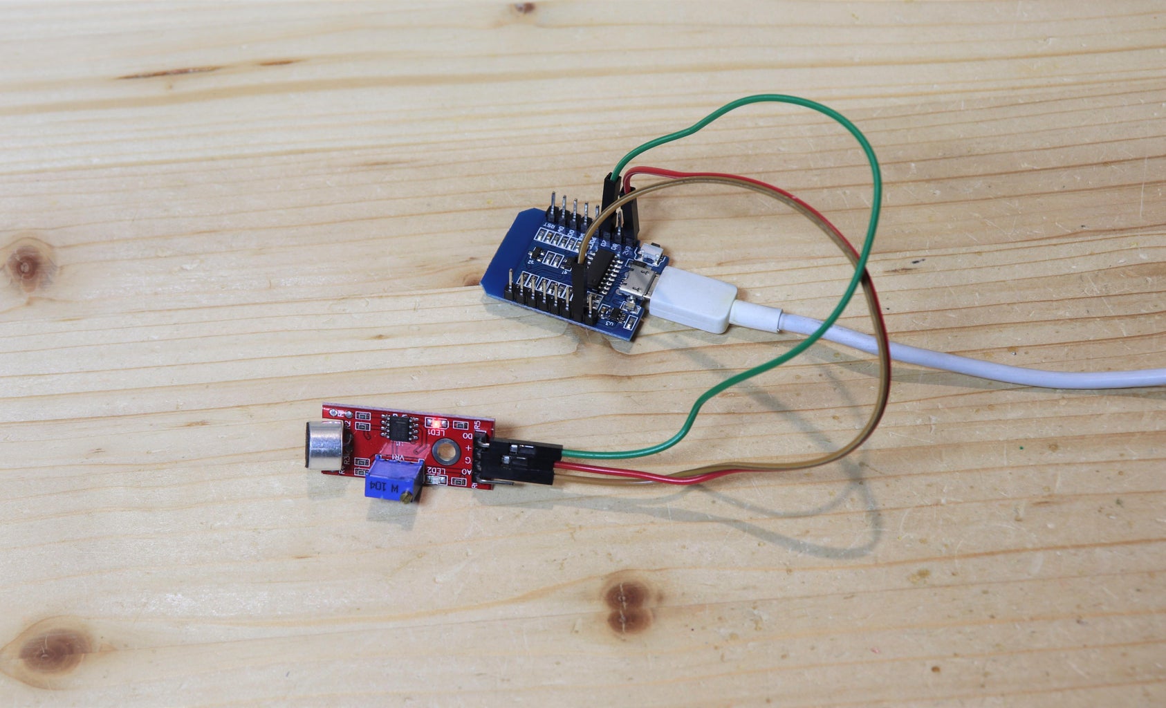
Using an ESP8266 As a WiFi Enabled Universal Remote Circuit Diagram Today in this project you will learn how to make IoT smart RFID door lock system using NodeMCU ESP8266, RFID MF-RC-522 Module, a Relay, Solenoid lock, and Blynk IoT platform. With the help of this project, you can remotely monitor your door lock from anywhere in the world using your phone. (Both iPhone and Android Devices). Here's the code so you can program your ESP8266 board. Step 6: Assambly: Wire up all the components together, install the electric lock, wire it to the enclosure and place the PCB and the power supply inside the box, close the lid and everything is almost ready.
Hey, Friends In This Video I Will Show You How To Make an Esp8266-based Door Lock System Using an Esp8266, Rc522 (RFID), and a Solenoid Lock.Code And Circuit

Smart Door Lock w/ WiFi Login Page by Arduino & ESP8266 Circuit Diagram
In this project, we will make a door lock with ESP8266. I use android app for this purpose. This app has two buttons, one is for lock and other is for unlock. You can set the value of lock and unlock button by pressing long. and you must change this value into the code. In this project, I am using hidden network, for wifi connection, Add

Learn how to make ESP8266 RFID/NFC Door Lock system, how to use RFID/NFC tag to unlock the door, how to make a security door lock system, how to program ESP8266 step by step. The detailed instruction, code, wiring diagram, video tutorial, line-by-line code explanation are provided to help you quickly get started with ESP8266. Find this and other ESP8266 tutorials on Newbiely.com.
IoT Smart RFID Door Lock System Using NodeMCU ESP8266 Circuit Diagram
We only stick a QR code on the door and the allowed people can scan it to see the login page and enter their password. After typing the password, the solenoid lock will be activated. We only use an Arduino board and a driver for the solenoid and an ESP8266 to make a connection to local wifi. Let's do it.